- 您现在的位置:买卖IC网 > Sheet目录264 > Z-01H55-B (Omron Electronics Inc-IA Div)BASIC SWITCH
�� �
�
�Tightening�
�The� suitable� tightening� torque� for� screw� terminals� is� given� below.�
�?� Screw� terminals� except� for� those� on� Split-contact� Models�
�(Z-10FY-B):� 0.78� to� 1.18� N� ·m�
�?� Screw� terminals� on� Split-contact� Models�
�(Z-10FY-B):� 0.49� to� 1.18� N� ·m�
�Operation�
�?� Make� sure� that� the� switching� speed� and� frequency� are� is� within� the�
�specified� ranges.�
�1.� If� the� switching� speed� is� extremely� slow,� the� contacts� may� not� be�
�switched� smoothly,� which� may� result� in� a� contact� failure� or� contact�
�welding.�
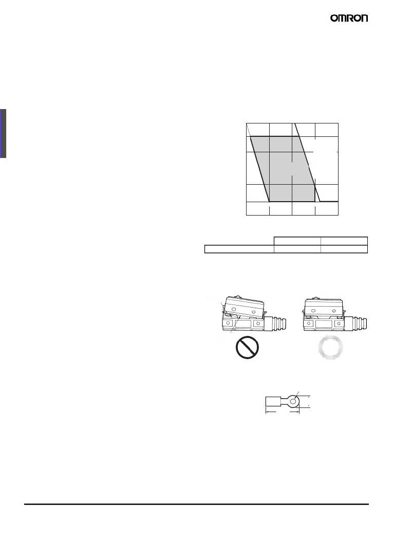
�Micro� Load� Applicable� Range�
�Using� a� model� for� ordinary� loads� to� open� or� close� the� contact� of� a�
�micro� load� circuit� may� result� in� faulty� contact.� Use� models� that�
�operate� in� the� following� range.� However,� even� when� using� micro� load�
�models� within� the� operating� range� shown� here,� if� inrush� current�
�occurs� when� the� contact� is� opened� or� closed,� it� may� increase� contact�
�wear� and� so� decrease� durability.� Therefore,� insert� a� contact�
�protection� circuit� where� necessary.�
�The� minimum� applicable� load� is� the� N� -level� reference� value.� This�
�value� indicates� the� malfunction� reference� level� for� the� reliability� level�
�of� 60%� (� λ� 60� ).� The� equation,� λ� 60� =� 0.5� ×� 10� -6� /operations� indicates� that�
�the� estimated� malfunction� rate� is� less� than� 1/2,000,000� operations�
�with� a� reliability� level� of� 60%.�
�2.� If� the� switching� speed� is� extremely� fast,� switching� shock� may�
�5� m� W�
�8� 00� m� W�
�damage� the� Switch� prematurely.� If� the� switching� frequency� is� too�
�high,� the� contacts� may� not� be� able� to� keep� up� with� the� speed.�
�30�
�0.16� mA�
�26� mA�
�Operating�
�The� rated� permissible� switching� speed� and� frequency� indicate� the�
�switching� reliability� of� the� Switch.�
�The� life� of� a� Switch� is� determined� at� the� specified� switching�
�speed.� The� life� varies� with� the� switching� speed� and� frequency�
�even� when� they� are� within� the� permissible� ranges.�
�Always� conduct� appropriate� durability� tests� under� actual� condi-�
�tions� before� using� a� Switch.�
�?� Make� sure� that� the� actuator� travel� does� not� exceed� the� permissible�
�24�
�12�
�Un� u� sa� b� le�
�range�
�Operating� range�
�for� micro� load�
�models� Z-01H�
�range� for�
�general� load�
�models�
�Z-15H,� H2�
�Z-15G�
�Z-15E�
�Z-10FY�
�Z-15ER�
�OT� position.� The� operating� stroke� must� be� set� to� 70%� to� 100%� of�
�the� rated� OT.�
�5�
�1 m� A�
�100� mA� 160� mA�
�Panel� Mount� Switch� (Z-15� @� Q� @� ,� Z-01� @� Q� @� )�
�0�
�0.1�
�1�
�10�
�100�
�1,000�
�?� W� hen� mounting� the� panel� mount� plunger� model� with� screws� on� a�
�side� surface,� be� careful� of� the� dog� angle� and� operation� speed.�
�C� u� rrent� (mA)�
�Excessive� dog� angle� or� operation� speed� may� damage� the� Switch.�
�?� W� hen� using� the� panel� mount� plunger� model� mounted� with� screws�
�on� a� side� surface,� be� careful� not� to� apply� a� large� shock.� Applying� a�
�Minimum� applicable� load�
�Z-01H�
�1� mA� at� 5� V� DC�
�Z-15� @� ,� Z-10FY�
�160� mA� at� 5� V� DC�
�shock� exceeding� 1,000� m/s� 2� may� damage� the� Switch.�
�?� W� hen� using� the� panel� mount� plunger� model� mounted� with� screws�
�on� a� side� surface,� remove� the� hexagonal� nuts� from� the� actuator.�
�High-sensitivity� Switch� (Z-15H)/�
�Extra-high-sensitivity� Switch� (Z-15H2)�
�?� W� hen� using� the� Switch� in� a� DC� circuit,� be� sure� to� provide� an� arc�
�suppressor� as� well� because� the� small� contact� gap� of� the� Switch�
�may� result� in� contact� troubles.�
�?� In� an� application� where� a� high� repeat� accuracy� is� required,� limit� the�
�current� that� flows� through� the� Switch� to� within� 0.1� A.� Also,� use� a�
�relay� to� control� a� high-capacity� load� if� the� Switch� is� connected� to�
�such� a� load.� (In� this� case,� the� exciting� current� of� the� relay� coil� is� the�
�Models� with� Drip-proof� Terminal� Cover� (Z-� @� A55-B5V)� Wiring�
�?� To� attach� the� Protective� Cover� to� the� case,� hold� the� cover� in� almost�
�parallel� to� the� case� and� then� push� it� to� the� case.� If� the� cover� is�
�pushed� diagonally,� the� rubber� packing� may� slip� off,� degrading� the�
�sealability� of� the� Switch.�
�Terminal� with�
�toothed�
�washer�
�Rubber� packing�
�load� of� the� Switch.)�
�?� Do� not� apply� a� force� of� 19.6� N� or� higher� to� the� pin� plunger.�
�?� Exercise� care� that� the� environment� conditions� such� as� temperature�
�and� humidity� do� not� change� abruptly.�
�?� Use� round� solderless� terminals� having� the� following� dimensions� to�
�connect� leads� to� the� terminals.� Tighten� the� screws� of� terminals� to� a�
�torque� of� 0.78� to� 1.18� N� ·m.� Use� the� terminal� shown� below.�
�4.3� dia.�
�8�
�20� max.�
�?� A� cable� 8.5� to� 10.5� mm� in� diameter� can� be� applicable� to� the� sealing�
�rubber� of� the� lead� outlet� of� the� Switch.� A� two-core� or� three-core�
�V� CT� cable� having� a� cross-sectional� area� of� 1.25� mm� 2� is� especially�
�suitable� for� this.�
�?� M4� small� screws� with� spring� toothed� washer� are� used� as� the� termi-�
�nal� screws.�
�170�
�General-purpose� Basic� Switch�
�Z�
�发布紧急采购,3分钟左右您将得到回复。
相关PDF资料
Z-10FW1Y55-BC
SWITCH DPDT 10A HINGE LEVER
ZL36W0000
SWITCH TOGGLE SUBMINI
ZPS100-24
PWR SUP AC-DC 24V 4.2A
ZWQ1305224/A
PWR SUP QUAD 5V/+12V/-12V/24V
ZWS150PAF48/J
PWR SUP 48V 4.3A 206.4W
ZWS240PAF24/TA
PWR SUP 24V 240W 10A W/COVER
0014441203
IDT OPT D MALE 24AWG 15SAU 3CKT
0014441204
IDT OPT D MALE 24AWG 15SAU 4CKT
相关代理商/技术参数
Z01HB
制造商:OMRON AUTOMATION AND SAFETY 功能描述:SWITCH SPDT 0.1A PIN PLUNGER
Z-01H-B
功能描述:基本/快动开关 Basic Switch
RoHS:否 制造商:Omron Electronics 触点形式:SPDT 执行器:Lever 电流额定值:5 A 电压额定值 AC:250 V 电压额定值 DC:30 V 功率额定值: 工作力:120 g IP 等级:IP 67 NEMA 额定值: 端接类型:Wire 安装:Panel
Z-01HD
制造商:OMRON 制造商全称:Omron Electronics LLC 功能描述:General-purpose Basic Switch
Z-01HD55
制造商:OMRON 制造商全称:Omron Electronics LLC 功能描述:General-purpose Basic Switch
Z01HD55B
制造商:OMRON AUTOMATION AND SAFETY 功能描述:BASIC SWITCH
Z-01HD55-B
功能描述:基本/快动开关 Basic Switch
RoHS:否 制造商:Omron Electronics 触点形式:SPDT 执行器:Lever 电流额定值:5 A 电压额定值 AC:250 V 电压额定值 DC:30 V 功率额定值: 工作力:120 g IP 等级:IP 67 NEMA 额定值: 端接类型:Wire 安装:Panel
Z01HDB
制造商:OMRON AUTOMATION AND SAFETY 功能描述:SWITCH SPDT 0.1A SPRING PLUNGER 制造商:OMRON INDUSTRIAL AUTOMATION 功能描述:Switch Snap Action N.O./N.C. SPDT Short Spring Plunger Screw 0.1A 125VAC 30VDC 2.45N Screw Mount
Z-01HD-B
功能描述:基本/快动开关 BASIC SWITCH
RoHS:否 制造商:Omron Electronics 触点形式:SPDT 执行器:Lever 电流额定值:5 A 电压额定值 AC:250 V 电压额定值 DC:30 V 功率额定值: 工作力:120 g IP 等级:IP 67 NEMA 额定值: 端接类型:Wire 安装:Panel